Saturday, April 18, 2009

Front upright and brake duct

It's been hard for me to keep with this lately, but last week Thursday, I got some more design time in.

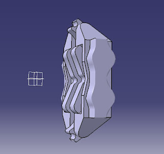
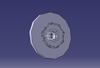
I have essentially completed the front upright


The upright as pictured above includes the brake duct. Here is the brake ducting completed as a separate part.


I haven't had a lot going on at work lately. I was searching for aftermarked parts for my current project (http://jordan191model.blogspot.com/) and found these tires made by Wolf Design on the Media Mix Hobby website out of Singapore (click here).


If you compare the above photo of the 1/20 scale part with the below picture of a Goodyear tire on a 1993 McLaren, the realism is supurb.


The availability of these tires is a game changer for me. Up to this point, I have been planning to design the whole car in CAD, get something like this, convert it to a CNC mill, design molds from my CAD parts, convert to G-Code, mill the molds, and resin cast the parts, use RTV rubber for the tires. I still believe that this method should be effective in general, but observing the detail on these tires by Wold Design, I can't figure out how I would repoduce such detail. Imagine the size of the drill bit I would have to put into the CNC mill to get this kind of detail. It's hard for me to believe that while milling metal a drill bit that small wouldn't break.

At present, I am now planning to buy a set of these tires and use them on the kit. They cost $31.74 including shipping to Poland, and to be honest, I don't think that I can match their level of accuracy for that price, at least until I have a bit of milling experience. The monocoque is a different story, for one because a model of this car is not available and must be prototyped, and for two, it doesn't involve the incredible level of surface recessing that these tires have.

This has serious implications for the work I've done so far. I have designed everything around the concept of 13 in scale wheels, in other words wheels that have a 16.5 mm diameter. The wheels I have designed will not fit for example into the Tamaya Jordan 191 tires, as the wheels in that kit have a slightly larger diameter. As I don't currently possess these Wold Design Tires, I don't know what their inner diameter is, and can't really design wheels until I do know. Furthermore, the size of the brakes/calipers/uprights/brake ducts is dependent on the inner diameter of the wheels for clearance purposes, so they are all designed thinking the outer diameter of the wheels would be 16.5 mm. If it is even a 0.5mm different, it changes all the design parameters. As such, it's back to the drawing board again. I've learned a lot about how do draw in CAD, the possibilities/limitations of different CAD programs, and this has been very beneficial. Considering the new tire possibilities, I think it's best for me to set this aside and begin working on another part of the car. That probably means it's back to the front wing/nose/monocoque/sidepods/undertray/cowling.

Total time: 230 h

Thursday, March 26, 2009

Putting the brakes on

Brake Caliper. Basically lots of 2d sketches, extruded. If someone told me I would learn how to do this, I would have never believed them.


Total: 225 h

Tuesday, March 24, 2009

My first part in the new CAD program

Isn't she lovely?!?!


Upon further review later, I think the radius is too big and I'll have to do some modifications. But I'm really excited that I managed to do this so well!

Total: 221 h

Monday, March 23, 2009

brakes and wheel hub

Did some rough drafts to understand relationships, shapes, and sizes.

Brake


Brake with wheel hub


Total: 217 h

Sunday, March 22, 2009

Reinventing the wheel part 2

Sketched the profile of the wheels. This CAD program is amazing, the wheel is geometrically perfect!


Total: 214 h

Saturday, March 21, 2009

Reinventing the Wheel part 1

Wow. Today I did more training in my new CAD program and designed the front and rear tires.


Total: 212 h

Thursday, March 19, 2009

Something new

I don't have much to show for myself here, but I've started working with a new CAD program. I was at a party with my girlfriend who introduced me to someone she knows who is an engineer at an auto company. He suggested I use a different CAD program. I'm giving it a try. I spent some time training and experimenting.

Total: 207.5

Saturday, March 7, 2009

figured it out.

Turns out the way I was making curves was causing the solid to be asymmetrical. I needed to make the curves in a start-end-direction fashion, so that the start could always be at the bottom, and the end always on the top. Made quite a bit of progress.


Total: 204.5 h

More nose cone work and a problem

I continued to work on the nose cone, adding section, and connecting them to make a solid shape.


I've run into a strange problem. Although my sections are perfectly symmetrical, the solid image is not, as can be seen from the wireframe view.


I think it's back to the drawing board on this nosecone. I know think I understand now that I need to use construction lines during the construction of my sections rather than normal lines. The CAD program seems to be saving the data from my lines even after they are erased. I am hoping if I begin using construction lines extending to infinity with no points, that there will be no data to ruin the symmetry of the solid model.

Total: 201.5 h

Friday, March 6, 2009

Nose cone

Started on the nose cone today.


Nose cone and front wing main plane together


Total: 199 h

Thursday, March 5, 2009

CAD

Designed the front wing main plane


Total: 197 h

Wednesday, March 4, 2009

CAD Design

To be honest, I sat puzzled at how I was going to begin for most of today, and decided I would start with the front wing.

Total: 195 h

What have I been doing

I haven't been sitting idle, but I think I can accurately say that I haven't accomplished anything either.

I designed the car well in CAD. My thought was to 2.5d manufacture it with Balsa. I got some thin strips of Balsa wood from a local model airplane shop.

First, I sectioned my CAD model every 0.5 mm.


Then I printed the shapes


Cut a form out


Cut some tape


Tape the cut out image onto the balsa wood


Drilled a couple of alignment holes


Holes now drilled


Used a razor blade to trace the image on the paper onto the balsa.


Paper is now cut.


Take the taped paper off


Use the razor to cut the image all the way out of the balsa.


Remove the balsa section


Placed on the guide pins.


Repeat. A lot. Stacked all the balsa sections up. Epoxied them together, and covered the whole thing in a thin coat of wax.


Here are my attempts. My "try again" garage.


In the end, this didn't work either. Problem is, when you stack up 96 pieces of .5mm balsa, it doesn't necessarily make a 48mm part. I was counting on the balsa being exact, and I think at that thickness, it's just too much to ask. My first model was too tall, my second attempt was too short. Anyway, I gave up 2.5d prototyping, and tried to make a tool from my balsa blank. I mixed the plaster with too much water, the plaster tool was too soft, and broke when I tried to reassemble it to pour a casting. I'm done. I'm done with doing this by hand, I'm done with plaster casting.

I'm going digital.

Total: 194 h

Wednesday, February 11, 2009

More plaster disasters and CAD

I haven't written for a few days...it's taken me some time to get over the disappointment of my molding failure. Here's what happened

Got ready to mix the ceramit.


Tried to pour it and everything went wrong. It was too thick, and my pour hole was too small. It kept on getting clogged in the gate. I didn't get a complete fill before the material dried. In retrospect, the gate and vent were poorly placed, I was never going to get a complete fill. Furthermore, I should probably study material sciences. The ceramit was a little harder than the plaster, so despite using olive oil as a mold release agent, the pour did not want to come free. When I finally saw the writing on the wall, I knocked it out with a hammer. This is what I got.


Here are my four attempts


Anyways, this failure led me to rethink my design process. I decided to give a go at designing the car in CAD. I'm amazed! Here are my results:


Total: 114 h

Friday, February 6, 2009

Tooling

I know this is long so bear with me

First I've got the box I made. I laid the car on it's side, and marked where the guide pins should be to not interfere with the form.


Drilled holes for the guide pins


Had to open up the holes a little bit with a file as I did not have a drill bit large enough.


Then put the guide pins in place. I accidentally bought one 2cm short, so oh well, there is a short one.


Then I drilled holes and placed the bolts that will hold the blank and act as the gate and vent in the finished tool


Painted the mating surfaces of the frame with wax so they wouldn't leak.


Placed my blank on the bolts I installed


And painted it with a light coat of olive oil. (probably didn't need to be extra virgin, but probably didn't hurt either!)


Then I assembled the side of the box with the attached blank


Getting the screws in place, just some final checks


We are ready for the first pour


The goal was to pour plaster halfway up onto the blank. This was much harder than it looks. I didn't mix enough plaster, so I had to make another batch.


I waited for this pour to dry, then painted it with olive oil as well


Second pour for the other half...jeez, again I mixed too little plaster. Next time I'll do some math and calculate volume before mixing


So here's what we got. I attached nuts to the top of the guide pins to hold it together (just in case)


First, I took the bolts for the gate and vent out of the side


Then removed the guide pins


Took off the bottom


And the sides


This is the result of my pours of plaster


Put a bolt back in a gave it a decided whack with a hammer (now that took confidence!)


Pryed the two halves apart with my hands, as I imagined that it was still quite delicate


And wouldn't you believe it worked


Ladies and gentlemen there you have it, I have made a tool


Pounded the guide pins back in place


Tightened them down, and will let this dry for a while


Total: 82 h