I'm going to design the nose - monocoque - cockpit - airbox in Autodesk Maya.
My logic is this:
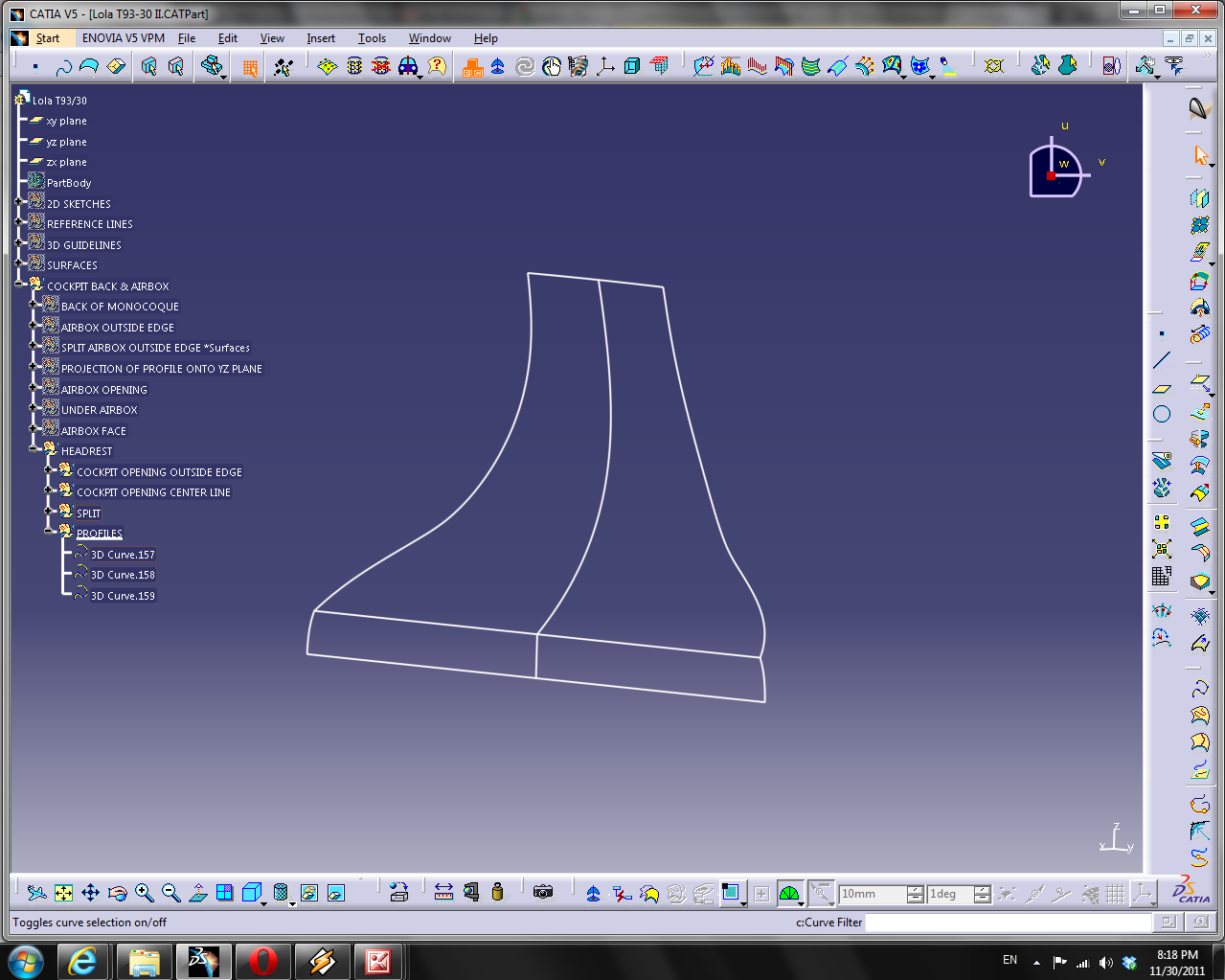
I've been explicit modeling these parts in Catia. This was not so much of a conscious choice, as I didn't know all the possible methods of creating these parts. So I initially figured that the best solution would be to do everything natively in Catia. I've had two problems with explicit modeling.
1) It's hard
2) The original car was not explicit modeled in CAD software.
The fact that it's difficult to explicit model is not so much of a problem psychologically to me. Kudos to you Class A surface engineers of the world working in ICEM Surf or Autodesk Alias. I've found it difficult to learn, and conceptually challenging, but entirely possible with patience. My big issue at the moment with my modeling method is that I'm not moving forward maintaining the kind of surface quality I want. This car of course was the poorest performing F1 car of 1993. It started life as a clay model, was 3d scanned, and then maybe some of the surfaces were tweaked just a little bit. About roughly a billion times I've wanted to reach into my monitor with my hands and shape curves with my fingers. I suppose that's what learning to model is like?
So here's the big idea:
Box model the nose - monocoque - cockpit - airbox in Autodesk Maya (yeah, I know not an engineering software) Point is to recreate the clay modeling process that created the real car. I'll wind up with a polygon mesh. I intend to transform this into a single NURBS surface. I intend to save it as in
IGES file. I intend to import this into Catia, and then chop it up as I need to. I intend to. We'll see what is possible with the time and software available.
Why Maya? Because I like this guy's tutorial.
Pixelbahn. It's enough for me. From all the research I've done, there's not a gigantic difference in the work that can be created with 3ds Max, Maya, Lightwave, Cinema 4d. I saw something about it being a bit easier to make NURBS surfaces in Maya, but whatever, everyone has an opinion on the internet. Having a descent tutorial on an interesting subject is good enough for me.
So, I'm going to go back to the beginning with my scanned kinda blueprints in Corel and make some usable images out of them.
1994 Technical Regulations
Yeah, I know they aren't the '93 regs, but close enough for my purposes
I'm going to make my reference images this time in 1/10 scale
1. Width:
The overall width of the car including complete wheels shall not exceed
200cm, with the steering wheels in the straight ahead position.
5. Overhangs:
No part of the car shall be more than than 50cm behind the centre line
of the rear wheels or more than 120cm in front of the centre line of
the front wheels.
Furthermore, no part of the bodywork more than 20cm from the
longitudinal centre line of the car may be more than 90cm in front of
the front wheel centre line.
The centre line of any wheel shall be deemed to half way between two
straight edges, perpendicular to the surface on which the car is
standing, placed against opposite sides of the complete wheel at the
centre of the tyre tread.
6. Height:
Except for the rollover structures, no part of the car can be higher
than 100cm from the ground. However, any part of the rollover
structures more than 100cm from the ground must not be shaped to have a
significant aerodynamic influence on the performance of the car.
Furthermore, any part of the car behind the centre line of the rear
wheels must not be more than 95cm from the ground.
All height measurements will be taken with the car in normal racing
trim with the driver aboard seated normally.
So I'll make my drawing a little bit bigger than this
I'm going to show the grid
Wheelbase can be found on
wikipedia. 3030mm
Side view of car regulations & wheelbase
With reference image scanned from book
Wheels. Front tires are Goodyear 25.5 x 9.5 x 13. Rears are Goodyear 26 x 13 x 13 (read off sidewalls)
In metric terms that is
Front: 647.7mm diameter x 241.3mm wide
Rear: 660.4mm diameter x 330.2mm wide
Something like that
Do I design the rake into the car from the beginning? I think I'm going to say no. I believe it'll be easier for me to keep everything from the reference plane (read floor) to the top of the wings at 90 degree angles. So lets modify the reference image so that the floor is parallel with the ground.

7. Aerodynamic influence:
Any specific part of the car influencing its aerodynamic performance:
- Must comply with the rules relating to its bodywork
- Must be rigidly secured to the entirely sprung part of the car
(rigidly secured means not having any degree of freedom).
- Must remain immobile in relation to the sprung part of the car.
Any device or construction that is designed to bridge the gap between
the sprung part of the car and the ground is prohibited under all
circumstances.
No part having an aerodynamic influence and no part of the bodywork may
under any circumstances be located below the geometrical plane
generated by the flat surface described in Article 3.3.
No part of the bodywork in front of the rear edge of the complete front
wheels and more than 25cm from the longitudinal centre line of the car
may be closer than 40mm to the geometrical plane referred to in Article
3.3.
- So the front wing endplates must be 40 mm above the reference plane
There are going to be some issues with this no matter how I do it. I don't have my data from Catia in this drawing. For example, I don't know what the bottom of the nose should look like. Anyways, this is all part of a learning process so whatever. I think this time instead of tracing the car in Corel and exporting the lines, I'm going to use the raw image. It's positioned well now, so I'll draw a big box around the car.
So I think now, I'll export this and open up the exported image in Photo Paint so I can crop it
The benefit of all this work is that I'll have two images, the side and the top, perfectly aligned for 3d modeling. Now on to the top view
What do we know about the top view.
1. Width:
The overall width of the car including complete wheels shall not exceed
200cm, with the steering wheels in the straight ahead position.
2. Width ahead of the front wheel centre line:
The bodywork ahead of the front wheel centre line is limited to a
maximum width of 140cm. Nevertheless, any part of the bodywork ahead of
the front wheel centre line exceeding and overall width of 110cm must
not extend above the height of the front wheel rims with the driver
aboard seated normally and irrespective of the fuel load.
3. Width and shape between the front and rear wheels:
The maximum width of the bodywork behind the centre line of the front
wheels and in front of the centre line of the rear wheels is 140cm.
So in front of the rear wheel centerline the max width of the bodywork is 1400mm
4. Width behind the rear wheel centre line:
Bodywork behind the centre line of the rear wheels must not exceed
100cm in width.
Unfortunately my top view scan isn't as good as the side view one, but it's close, oh well, what can you do
Cropped


