Right now I'm working towards making loft 1 - nose, monocoque & cockpit top.
The nose intersects with the front wing. It'll be useful to have the side profile of the front wing I earlier designed to guide in designing the nose. F1 cars are designed to optimise airflow from the front to the back. I would highly recommend starting by designing the front wing and working back from there. So I'll open up my front wing and insert a sketch on the zx plane. Project 3d elements onto the sketch plane.
Copy this sketch and paste it into a new geometric set in your model.
In the same way that I created ALL BODYWORK TOP PROFILE, I'll now create the upper side profile of the nose and monocoque, using a new geometrical set.
Might as well create the upper side profile of the airbox as well while I'm at it. Note, I'm deviating here from the drawing that I scanned out of the book, as all the reference photos I have seem to indicate a lower airbox spine.
Next up will be the side view of the sidepods
Every curve on the 3d surface I'll be making gets it's own guideline. Next up will be the middle guidelines. Note the line on the 2d sketch is a reflection line. This line that I create needs to take into account that the sidepod mating to the monocoque should be a straight line as viewed from above.
Now a dividing line which will divide the the upper nose and monocoque loft from the lower one (see first drawing in post)
Actually the though just occurred to me now to arrange my reference lines into side profiles and top profiles. Create a new geometric set SIDE PROFILES and change the geometric set of all side profiles. Create TOP PROFILES as well
Couple more side profiles here. These are for the underside.
Time to look at the TOP PROFILES. Hide the SIDE PROFILES, we don't need them for now. I'm going to create NOSE-MONOCOQUE-AIRBOX TOP PROFILE ON SIDEPODS. Create a new geometric set, add a set "POINTS" underneath it. I'm going to cut the ALL BODYWORK TOP PROFILE 3d curve (non-destructive editing, the original line is still intact). First, insert a point at X=-1599mm and make an infinite line through this point in the direction of the zx plane. Then in the Generative Shape Design workbench, use the split command to split the ALL BODYWORK TOP PROFILE 3d curve with the infinite line we just created as a cutting element.
This method ensures that from the front of the car until the split, the line is exactly the same as the lower profile. It also allows us to keep the lower profile for use later. The act of splitting this 3d curve will hide it, unhide it in the tree.
I'm also going to create a new line under DIMENSIONS. This will be the an infinite line through the point created on the ALL BODYWORK TOP PROFILE at the intersection point with SIDEPODS MATING WITH MONOCOQUE in the yz direction.
Now I'll go about the normal process of creating control points, using this newly created dimension as a reference
In the Freestyle workbench, create a 3d curve starting at the end of the split we earlier created.
Back in the Generative Shape Design workbench, join the previous split with the new 3d curve.
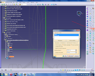
I think this next step is hugely important in creating clean surfaces using this technique. Smooth the joined curve. The smooth button can be accessed in the same place where "join" can be found. Highlighted in orange is a curvature discontinuity.
Set the Curve Smooth Definition to smooth curvature and use the smallest Maximum Deviation necessary to smooth the curve, as evidenced by a green box notifying us that a vertex has been erased.
Now go to the "Freeze" tab, and freeze the part of the joined curve that was created with the earlier split.
Having frozen the first part of the joined curve, we have exactly preserved the tangency, curvature and length of the ALL BODYWORK TOP PROFILE curve. Any deviations occur on the 3d curve we created.
I'll need to repeat this process again to create another curve that will be the lower guideline for the 1st loft. This line will be cut using the SIDEPODS MATING WITH MONOCOQUE dimension.


No comments:
Post a Comment