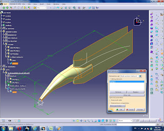
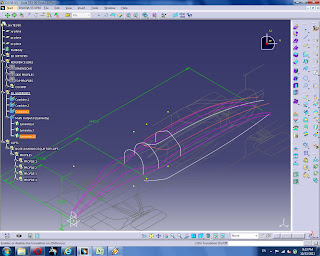
Two profiles is enought o create a loft. Go to the Generative Shape Design workbench. Create a Multi-Section Surface. Select the two profiles we created.
This isn't so precise though, and doesn't take into account the guides that we created. Delete the multi-section surface.
Insert a new geometric set 3D GUIDELINES.
Use the Combine command to combine the side and top guidelines one by one to create 3d guides.
Repeat for the bottom guide and then mirror using the symmetry command on the zx plane. We are only interested in one side of the car, so why do both? It seems to me that doing both sides at once produces the best surface across the centerline. I'll cut the model in half and mirror it later. For now, we'll design in symmetry.
Hide the REFERENCE LINES that don't intersect with the profiles. Create a Multi-Sections Surface under the NOSE & MONOCOQUE TOP LOFT geometric set.
Now, one by one add the guides, previewing after each to make sure that everything has been done correctly up to this point and the guides intersect the profiles.
This surface is a great start. Move the profile back to where the roll hoop starts.
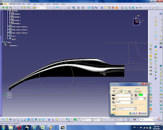
Hide all the lines. Start the Automotive Class A workbench. Use the ACA highlight command. This is a nice way to analyze the quality of the surface we created.
Alright. I'm going to cut the cockpit opening out of this, to see what it looks like from the top and the sides. In REFERENCE LINES under COCKPIT create a new geometric set CUTTING SURFACES and LINES under that. Create a symmetry of the COCKPIT - TOP PROFILE across the zx plane.
Join these two curves and smooth them. Create a line on one of the endpoints in the direction of the xy plane so that the line is taller than the monocoque.
Sweep the smoothed curve using the line we just created as a guide.
Cut the loft using the sweep we just created.
Hide the sweep and all the lines except our 2D SKETCHES.
Analyzing this, cutting from the bottom doesn't produce the desired result because the cockpit opening guides were not used to create this Multi-Sections Surface. So just as we created the profiles before, we need to add points on the cockpit opening lines to the profile, and we'll need a profile before the cockpit, and profiles "in" the cockpit.
Mirror this point we've just created and connect our profile to it.
Copy this profile and paste it under the PROFILES geometric set. There should be two profiles in the cockpit and two profiles out of the cockpit
We'll use the combine command to create 3D GUIDELINES from our cockpit profiles.
Create a Multi-Sections Surface using the two profiles outside the cockpit.
Create a Multi-Sections Surface using the two profiles inside the cockpit.
Create a Multi-Sections Surface closing the two surfaces we just created. Use the profiles 2 & 3 from the front, clicking on the surfaces when adding the profiles to the Multi-Sections Surfaces to add tangency to the surfaces already created.
Join all the surfaces together and hide all the lines except the 2D SKETCHES
Cut this joined surface with the REFERENCE LINES - COCKPIT - CUTTING SURFACES
Kick this into Class A Surfaces and do ACA highlight analysis again.
Looks good to me. I have one adjustment I'd like to make on the 3rd Profile.
I'm going to remove the tangency and curvature from this point
Turns out I did the same to the 2nd profile, and here is my surface now.


No comments:
Post a Comment