Monday, October 22, 2012

ICEM SURF v

Good morning. Some thoughts after yesterday's post: If I'm starting to get the hang of how to use control points, lets put this to the test and make a design that is easier to work with. I really only need to design half at a time because the car is symmetrical down the middle.

How about working on support? This way I won't have to create so many points.


I'm just going to make four points in a square using support. Wherever.


And a four point patch using these points


Hit control points and change this to 5 control points in the direction away from the centerline.


Select the 4 left control points to make G3 continuity across the centerline and set diffusion to constant law.


Change to the front view and move it on up


I'm going to change the color of this surface because I'm getting annoyed with how hard it is to see white again this surface


That's better

Set this guy to G3


Set Nv to 8


Clear to see these new control points are not aligned properly for G3 continuity


But that is fine, they can be edited.

By selecting the points on the bottom, right clicking and hitting edit, I can see where they are located.


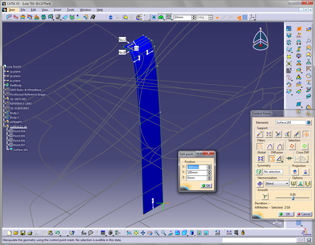
So now it's just a matter of making sure x and y are the same all the way up. I guess it would be good if z were evenly spaced too.


Something like that

 
So if I highlight all these points


I can edit the x position to -2200


Might as well move everything else back too


And might as well widen it out


Raise it up


And tighten up the curve a bit. I'll have to change the diffusion to "linear law"


There we go


Move those guys on the center line up to 705


This is going to get tricky now. I know the profile of the cockpit opening based on the 1993 FIA yellow book, so I'm going to draw it in 2d.

There we go


Alright, so I'll project this line onto my surface


Here I can see that I need to alter the shape of this surface, to lower the intersection to match my drafts.


So changing the diffusion law to linear and selecting all four control points, I can now start to lower the projection


Looks nice here:


But not here:


That's a little better, but I think I could use another control point


So set these ends to G3


And add another control point


That's pretty close to what I'm after

 
Looks good here


And here


So that is my starting point. I need the thing to start curving down at the bottom


So I'm going to back it off a bit


Extrapolate the edge

 
I'm only going to extrapolate it 100mm, so that I can set the G3 continuity and set up 5 control points


Now that fifth control point in the the v direction I'm going to manipulate to start making a shape

Something like that

 
Extrapolate again


Repeat


Keep extrapolating and adjusting


Ok.

Not working. Just because these are G3 surfaces doesn't mean they are nice.

I don't like the look of this analysis

Sunday, October 21, 2012

ICEM SURF iv

After 35 more tries, I've got a Class A solution and I don't like it because:

1) It's explicit
2) It's hard to work with

Rocking out to Cherub - "Doses and Mimosas"

Take the two spots where the sides are visually straight


Put a couple of straight lines there


Put a couple points on these lines at a ratio of 0.5


Make straight lines using these halfway points


Couple of verticle lines using the same points


Couple of sweeps


Hide all the lines and blend


Make symmetrical, hide initial support surfaces


Another blend


Hide the support blends and extrapolate from an edge


So check this out. Connection checker


Catia says it's G3.

How about we hide the blend and just look at the extrapolate from above.

Now you see it


Now you don't


Because that extrapolation is perfectly straight vertically. It's not hidden as can be seen in the tree


Ditch the extrapolation, we don't need it. Now the fun begins


If you hit control points, it will create another surface. Let's think about what we actually see here. The first control point represents point continuity, G0. The second point tangent continuity, G1, as it's exactly verticle in the z direction to the first point. The third control point represents curvature continuity, G2 as it is the third point exactly verticle and evenly spaced in the z direction. Lastly is the fourth control point, evenly spaced, verticle in the z direction from the other points, acceleration continuity, G3. Neato.

Notice that same level of continuity is not represented in the x direction using this method


So if I extrapolate in that direction, I'm not going to like what I see


G3 continuous? Yes, but hardly what I intended. So lets get the the insanely hard non-parametric work.

I need four control points perfectly spaced in a line at the start and finish in the z direction

I'm going to snap this stuff to points I create. This is going to take forever

First a couple of infinite guidelines on a plane at a height of 500 (the same as my earlier sweeps)

Yeah so, below we can see that the plane is the same height as the sweep profile line


Here are my points recreated on this plane. I suppose I could have done everything from the beginning on a movable plane, oh well


Couple infinite lines


Actually, now that I think of it, this is going to be rough working with mathematically. Crap. Because I put points on a line with a ratio. Ditch this idea. Restart without the ratio. I need to know exactly where the x points are. Ugh.

This was the point that was going to be problematic. Now set to x=-200.

I'll just recreate all those support surfaces quickly.


Alright there we go. So next order of business. Click on control points, I'm going to need the max that Catia v5 has to offer in the v direction (trust me, I've tried 36 times)

Select the surface, click on control points, right click on Nv:7


Select 16. Catia automatically harmonizes 16 points in the v direction


My shape starts at x=-200 and ends at x=-2000. Difference 1800. 1800/16=112.5. There is a control point in the v direction every 112.5mm.

That's a bunch of nice, evenly spaced points, 112.5mm away from each other


What I've done here is make a line from the this row of points up to the infinite lines that I want to use as my guides for creating G3 continuity.


Now made points at a ratio of 1 on these lines.


Crap. Should have divided 1800 by 15 = 120. The points should be spaced by 120. Oops. Reworked.

Anyways, we can see this now pretty much lines up.


Alright so check this out. The end points are fine, they must line up due to G0 (point) continuity. Start from the second one.

Selected all eight points in that make up the G1 control points in the v direction

 
Make the zx plane the symmetry plane. Unclick the symmetry button for the moment.

 
Select Manipulators Snap


Select the point at the bottom


Reframe on the point we created


Snap to this point


Now hit symmetry and the points on the other side should snap into place

 
Repeat for the next two sets of control points (G2 & G3)


btw: it makes no sense, but I swear to god, this manipulator snap function only works properly in the top view...this view


Anyway, extrapolate from the edge to see what we've accomplished.


As compared to this before we started messing around with the control points


Moral of the story: we're succussfully manipulating G3 connections

Here is the change up front

Before:


After:


ahhh, time consuming. Enough for today