Sunday, October 23, 2011

F1 car design in Catia V5 iii

As far as strategy goes, I'll be using lofts to create 3d surfaces. I'm going to separate 4 major sections of the car, as of course they are all connected, but represent significantly different shapes.


Right now I'm working towards making loft 1 - nose, monocoque & cockpit top.

The nose intersects with the front wing. It'll be useful to have the side profile of the front wing I earlier designed to guide in designing the nose. F1 cars are designed to optimise airflow from the front to the back. I would highly recommend starting by designing the front wing and working back from there. So I'll open up my front wing and insert a sketch on the zx plane. Project 3d elements onto the sketch plane.


Copy this sketch and paste it into a new geometric set in your model.


In the same way that I created ALL BODYWORK TOP PROFILE, I'll now create the upper side profile of the nose and monocoque, using a new geometrical set.


Might as well create the upper side profile of the airbox as well while I'm at it. Note, I'm deviating here from the drawing that I scanned out of the book, as all the reference photos I have seem to indicate a lower airbox spine.


Next up will be the side view of the sidepods


Every curve on the 3d surface I'll be making gets it's own guideline. Next up will be the middle guidelines. Note the line on the 2d sketch is a reflection line. This line that I create needs to take into account that the sidepod mating to the monocoque should be a straight line as viewed from above.


Now a dividing line which will divide the the upper nose and monocoque loft from the lower one (see first drawing in post)


Actually the though just occurred to me now to arrange my reference lines into side profiles and top profiles. Create a new geometric set SIDE PROFILES and change the geometric set of all side profiles. Create TOP PROFILES as well


Couple more side profiles here. These are for the underside.


Time to look at the TOP PROFILES. Hide the SIDE PROFILES, we don't need them for now. I'm going to create NOSE-MONOCOQUE-AIRBOX TOP PROFILE ON SIDEPODS. Create a new geometric set, add a set "POINTS" underneath it. I'm going to cut the ALL BODYWORK TOP PROFILE 3d curve (non-destructive editing, the original line is still intact). First, insert a point at X=-1599mm and make an infinite line through this point in the direction of the zx plane. Then in the Generative Shape Design workbench, use the split command to split the ALL BODYWORK TOP PROFILE 3d curve with the infinite line we just created as a cutting element.


This method ensures that from the front of the car until the split, the line is exactly the same as the lower profile. It also allows us to keep the lower profile for use later. The act of splitting this 3d curve will hide it, unhide it in the tree.


I'm also going to create a new line under DIMENSIONS. This will be the an infinite line through the point created on the ALL BODYWORK TOP PROFILE at the intersection point with SIDEPODS MATING WITH MONOCOQUE in the yz direction.


Now I'll go about the normal process of creating control points, using this newly created dimension as a reference


In the Freestyle workbench, create a 3d curve starting at the end of the split we earlier created.


Back in the Generative Shape Design workbench, join the previous split with the new 3d curve.


I think this next step is hugely important in creating clean surfaces using this technique. Smooth the joined curve. The smooth button can be accessed in the same place where "join" can be found. Highlighted in orange is a curvature discontinuity.


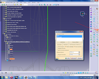
Set the Curve Smooth Definition to smooth curvature and use the smallest Maximum Deviation necessary to smooth the curve, as evidenced by a green box notifying us that a vertex has been erased.


Now go to the "Freeze" tab, and freeze the part of the joined curve that was created with the earlier split.


Having frozen the first part of the joined curve, we have exactly preserved the tangency, curvature and length of the ALL BODYWORK TOP PROFILE curve. Any deviations occur on the 3d curve we created.

I'll need to repeat this process again to create another curve that will be the lower guideline for the 1st loft. This line will be cut using the SIDEPODS MATING WITH MONOCOQUE dimension.


Saturday, October 22, 2011

F1 car design in Catia V5 ii

Define ALL BODYWORK TOP PROFILE as "in work object" so that the new line we create appears under this geometric set. Now I'm ready for my first 3d curve. The points on this curve should be the ends of the lines we earlier created.


Now double click on the line just created. Right click on all the points that are on the ends of straight lines and impose tangency. Impose curvature as well.


Before I go further, I'm going to need some other DIMENSIONS. Add a geometrical set under DIMENSIONS "NOSE & MONOCOQUE MATING LINE" Switch back to the Generative Shape Design workbench for this. Create a point by coordinates at X=-755. Constrain it to plane yz. Put a couple of infinate lines through it.


This next DIMENSION is one of the keys to the project. It's hyper important for this model. Insert a geometric set SIDEPOD MATING WITH MONOCOQUE. This line will be used a ton later. Change to a side view, add a point, constrain it and put a couple of infinate lines through it. The lines should be at the frontmost point of the sidepods.


Actually, now that I think of it, it would be useful if the lines and points in Dimensions looked different. Right click on DIMENSIONS geometric set, select properties, makes some changes.


Ok, moving on. As can be seen below, we need to add some more points on this 3d curve, as it doesn't match up with our drawing.


Define ALL BODYWORK TOP PROFILE - POINTS as the in work object. Hide the 3d curve under ALL BODYWORK TOP PROFILE, to make it easier to see our 2d sketch or drawing of the car. Add a point on NOSE & MONOCOQUE MATING LINE and change the distance on the line until it lies on the 2d sketch


Do the same using SIDEPOD MATING WITH MONOCOQUE.


Unhide the 3d curve under ALL BODYWORK TOP PROFILE, double click it to edit, click the circled button to insert a point, click on the 3d curve in between the points where you want to add a point, and constrain you new point on the points we just created.


We're getting closer to matching the 2d sketch or drawing. Add some more points on the 2d sketch or drawing and attach the 3d curve to them. This is going to take time and some trial and error. It's worth noting that it's really important that all the points are Z=0. This line has to lie on the Z plane.


Go through and ensure that all the tangencies on this 3d curve are set to norm = 1mm for now


Now I'm going to add a tangency and curvature restraint on the 3d line at the point we set on SIDEPOD MATING WITH MONOCOQUE to smooth everything out so that it matches our 2d sketch or drawing.


Looks good up front. How about at the back? As it is now, our 3d curve doesn't match up to our sketch.


Edit the norm of the tangency on the 3d curve so that it matches the sketch.


Hide ALL BODYWORK TOP PROFILE - POINTS, and we are left with a nice 3d curve.


I you can achieve similar results using a different method, go for it. I think this could be reproduced using a spline in the sketcher bench. I find this method much easier because I'm more familiar with using programs like Corel Draw to create vector graphic curves. I'm highlighting this method in detail because it took forever for me to learn, and I'll be using it extensively moving forward.

Friday, October 21, 2011

F1 car design in Catia V5

Alright, here we go!

First things first. I have a book about the car I'm designing.

The Modern Formula 1 race car - Nigel Macknight ISBN 0-87938-823-4

In this book, there is a drawing of the car from the top and the side.


I took the book to a copy shop and made great quality scans. Then I took those scans into Corel Draw and cleaned them up, creating vector graphic drawings of the essential lines.


Then I imported these images into Catia V5R21 SP1. For a nice tutorial on how to do this, look here:


Problem is, I don't have front or rear sketches of the car.

Fire up Catia. Create a new part:


Make sure "Enable Hybrid Design" is unchecked


At some point in the past, I converted the Corel Sketches I had into drawings in Catia, but this is an unnecessary step. I'm going to insert that geometrical set now, but as I say, it's unnecessary. Good enough to follow the above linked tutorial on how to insert images.


My goal in designing this car is to make the simpliest possible design using the fewest points and lines, as clutter free as possible. I'll be inserting lots of geometric sets and using the tree extensively. Insert a geometric set.


Ok, let's define the total length of the car first. According to the Formula One Technical Regulations of the time ARTICLE 3.5 BODYWORK AND DIMENSIONS - Overhangs:

No part of the car shall be more than than 50cm behind the centre line of the rear wheels or more than 120cm in front of the centre line of the front wheels.
Furthermore, no part of the bodywork more than 20cm from the longitudinal centre line of the car may be more than 90cm in front of the front wheel centre line.
The centre line of any wheel shall be deemed to half way between two straight edges, perpendicular to the surface on which the car is standing, placed against opposite sides of the complete wheel at the centre of the tyre tread.

According to Wikipedia http://en.wikipedia.org/wiki/Lola_T93/30 the wheelbase of the car is 3030mm.

If we assume that the designer would use the maximum amount of overhang for the front and rear wing (which they probably would) that would make the total length of the car (max front overhang + wheelbase + max rear overhang) = 900mm + 3030mm + 500mm = 4430mm. Working this out on my Corel sketches derived from the scan out of the book, it appears to be correct.

I'll insert another geometric set "DIMENSIONS" and within that geometric set, another I'll call REARMOST POINT


Open Start -> Shape -> Generative Shape Design and click to create a point


Create a point at X=-4430


Now I'm going to enter a constaint on the point with the distance from the yz origin (I think this is unnecessary, but good practice)


Next I'll create an infinite line through Point.1 in the direction of the xy plane.


And another in the direction of the zx plane. I'm doing this because I'm going to anchor other points and lines on these infinite lines to ensure that no lines are too short, or too long later.


Add another geometric set MAXIMUM BODYWORK WIDTH. According to the Formula One Technical Regulations of the time ARTICLE 3.3 BODYWORK AND DIMENSIONS - Width and shape between the front and rear wheels:

The maximum width of the bodywork behind the centre line of the front wheels and in front of the centre line of the rear wheels is 140cm.

So assuming the car is symmetrical 1400mm / 2 = 700mm

I'll place a constrained point and another infinite line at Y=700mm. No need to mirror this or repeat it on the other side, as we'll really only be focusing on designing one side of the car


This should be enough for me to now draw the profile of the car as seen from above.

Insert a geometric set under REFERENCE LINES, "ALL BODYWORK TOP PROFILE." Under this I'll insert a geometric set "POINTS."
Change to the Start -> Shape -> Freestyle workbench.
Change to the top view.
Right click on the compass and check "Lock Privilaged Plane Orientation Parallel to Screen"
Now I'm going to put a point on the scanned sketch at -500 to get started.


I'll add another point at X=0 Y=112 and connect the two points with a line.


Now, double clicking on the point at X=0, I can put the curser into the Y= dialog box and using the directional arrow keys on the keyboard move the point in until the line matches up with that on the sketch


This line (and a few others I'll create) will help to set tangency and curvature of freestyle curves I'll be drawing later. Hide the points, they are no longer necessary, it's the line I'm after. Repeat this process for any other straight lines, like the sidepods, and the rear deck. Hide the DIMENSIONS geometric set for now.

1994 Formula One Technical Regulations

I found a copy of the 1994 Formula One Technical Regulations here:

http://ccnga.uwaterloo.ca/~jscouria/technicalregs.html

not the '93 regs, but as far as body shape goes, should be good enough to design a '93 car.

disclaimer, getting started

Ok, so I'm going to start doing a step by step on how to design a f1 car in Catia. This has been for the last year, and will continue to be a huge learning adventure. This tutuorial is for a novice, I make no representation of being a f1 surface engineer.

Also, please remember, I am making no attempt to design a real formula one care. The goal of this exercise is to make a 1:20 scale model, that could be manufactured and assembled. I'll be designing this in 1:1 scale to give the greatest accuracy and flexibility with the goal of shrinking it to 1:20 later.

I was stuck for a long time, because I couldn't figure out how to do what I wanted to do. This tutorial kick started me. Worth taking a look at:


http://www.cadtutor.net/forum/showthread.php?53691-Free-CATIA-tutorial-8-(2010-New-release)-Rebuild-Audi-R8-(1-1)

Also worth seeing this:


http://toyotatf105.free.fr/index_english.html
So, turn off the lights, kick back, and listen to this Ferrari V12 before we get started: http://www.youtube.com/watch?v=c-rNiswUhQ4

BIRP! - the official music of me working in CATIA V5 shape

http://www.birp.fm/ recommended