
First step, create a new geometric set, join some surfaces

Hide the front part, we don't need it for now. Unhide REFERENCE LINES - SIDE PROFILES - SIDEPODS SIDE PROFILE
Cut and paste the REFERENCE LINES - SIDE PROFILES - SIDEPODS SIDE PROFILE down below, rename and move all the points 25 down the z axis

So to aid in the creation of fillets, I'd like this line to remain at the same y= distance on the airbox all the way to the back

I'll use the same method to get a 10mm offset on REFERENCE LINES - SIDE PROFILES, NOSE-MONOCOQUE-AIRBOX SIDE PROFILE MID

Time to connect these lines. I'll split both of them, draw a 3d curve with imposed tangency and curvature, join and smooth them. Where to split? My reference photos indicate the top of the monocoque sides are essentially flat to the back of the monocoque. So the first split will be at the back of the monocoque. For this I'll need a new REFERENCE LINES - DIMENSIONS.

Split the SIDEPOD OFFSET with REFERENCE LINES - DIMENSIONS - MONOCOQUE BACK
We'll have to split the SIDE PROFILE MID OFFSET somewhere behind it so that we create a nice smooth curve.

Create a 3d curve imposing tangency and curvature on both ends, join and smooth

We're going to have to split this again, because the "tip" of the top front of the monocoque sides has to slope down to make the fillets smooth as the fade into the monocoque.

I'm just going to "eyeball it" at the moment, this curve can be refined later as necessary

This line is going to have to extend so that it completely splits the front part of the nose-monocoque

Create a sweep using this line and split all computing intersections

Project the computed interesections onto the xy plane

Unhide REFERENCE LINES - DIMENSIONS and REFERENCE LINES - TOP PROFILES - MONOCOQUE TOP PROFILE

Trust me, there is a point to all this. Split MONOCOQUE TOP PROFILE somewhere behind DIMENSIONS - SIDEPODS MATING WITH MONOCOQUE.

Create a 3d curve to connect the two imposing tangency and curvature

Join and smooth it, this is our top view guide, tangent to the front nose and monocoque surface
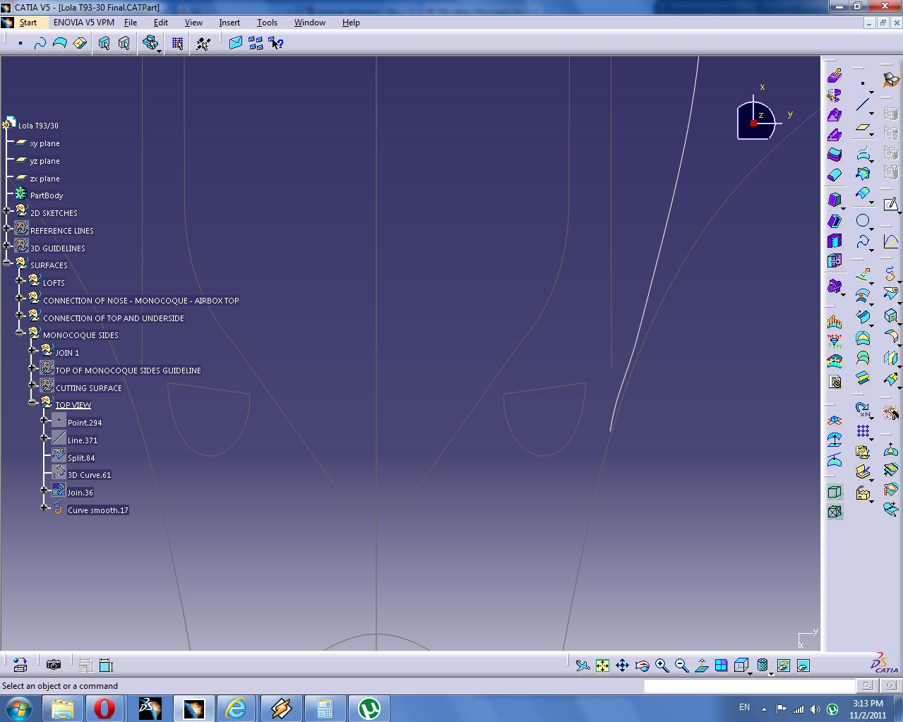
Combine the TOP VIEW we just created with the side view we earlier made

Unhide the relevent surfaces
Unhide the lower 3D GUIDELINE that roughly corresponds to the y= of the 3D GUIDE we just made. Extract the edge of the front part of the monocoque between the guide lines and split it at the guidelines.

Unhide the TOP VIEW where we split one of the original guidelines. The point as which it was split is exactly the point where the top and lower 3d guides have exactly the same y value.
Create a line up to the smoothed curve and put a point on it.

Create a line in the direction of the xy plane that intersects both guides.
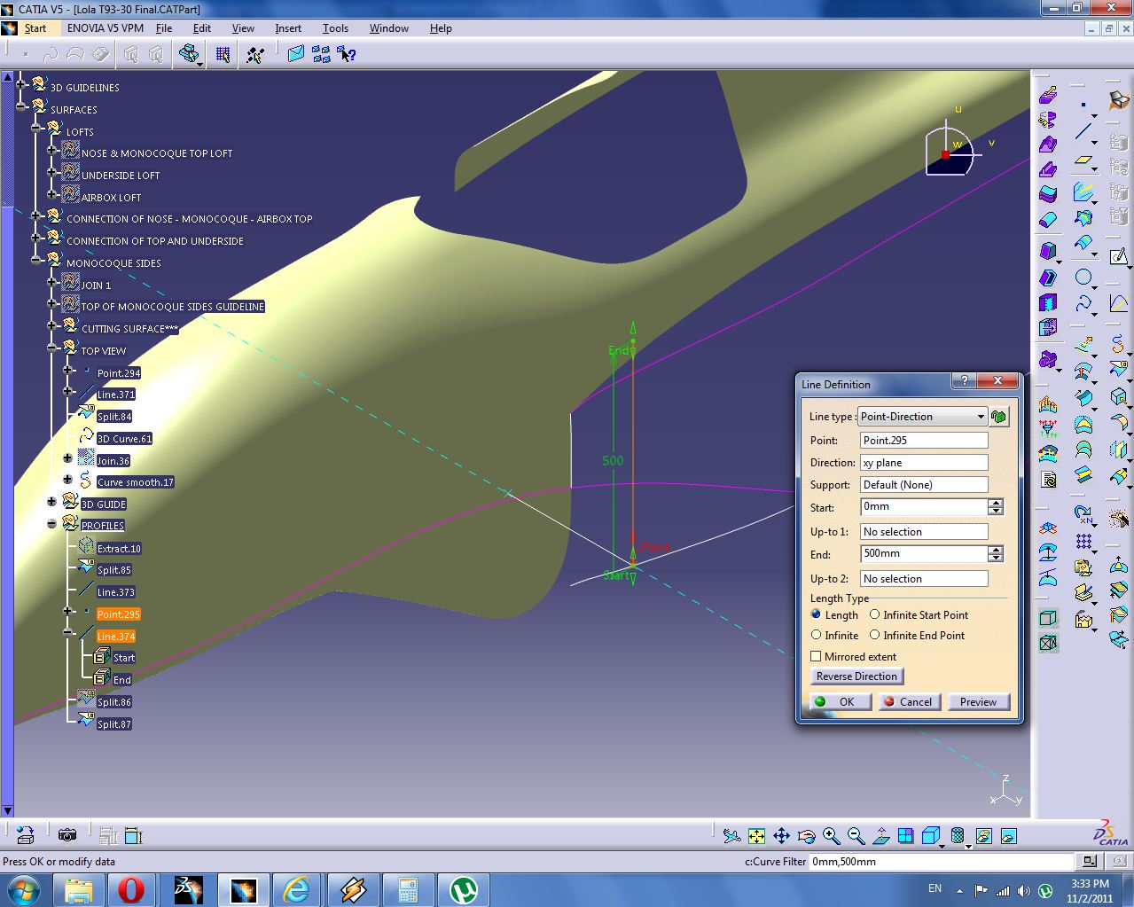
Split this line using the guides

One more line connecting the end points of the guidelines

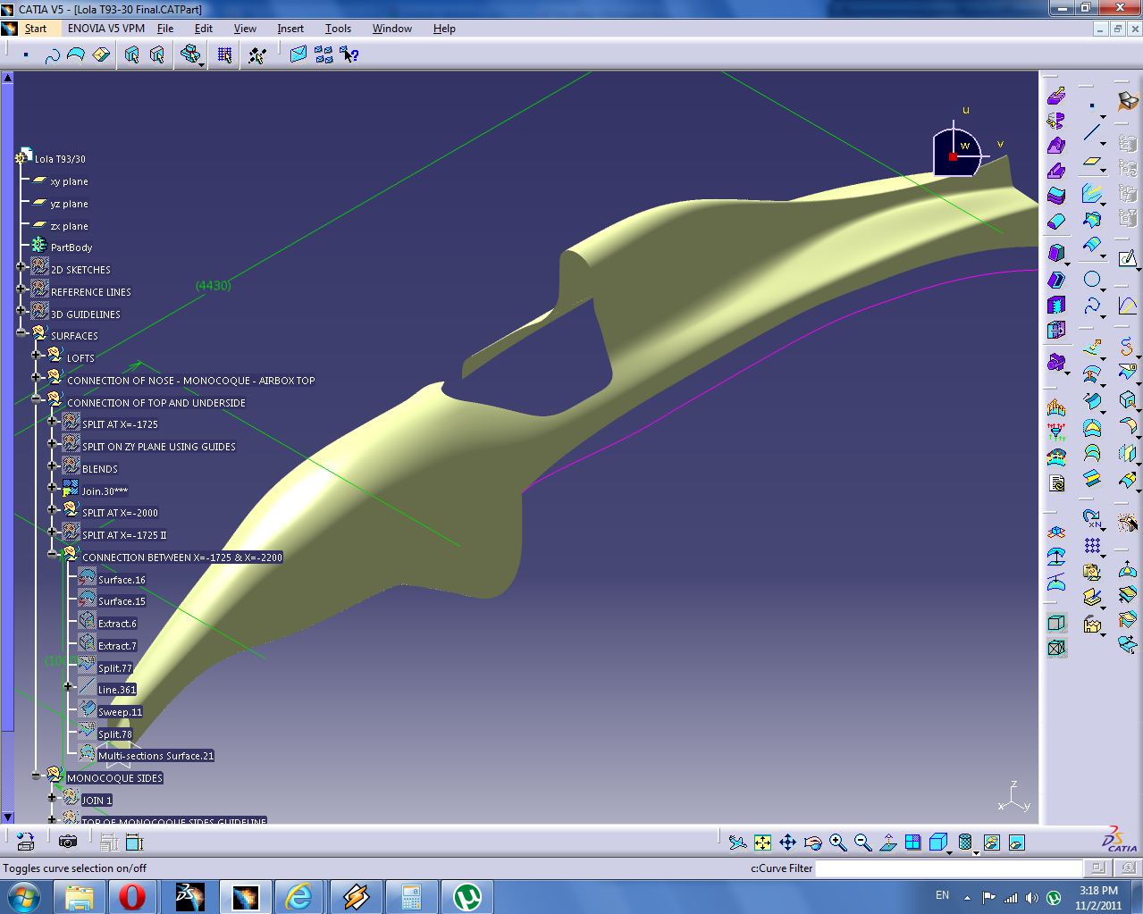
Alright lets finally make some multi-section surfaces. Unhide the SURFACES - LOFTS - UNDERSIDE LOFT. Create a multi-section surfaces using the middle and back profiles, using the guides we created, where the bottom guide is tangent to the existing surface.

And create another multi-section surface using the first two profiles, curvature continous with the adjacent surfaces, using our guides, where the bottom guide is tangent to the existing surface.

That was a lot of work, but good lines make good surfaces.

I think that is enough for one post.
No comments:
Post a Comment