Lola would have had a championship crushing car if they would have had 10 years, a million hours of labor and an unlimited budget to design this car. They didn't. I don't either.
I've learned a ton, but it's time to start thinking what comes after the surface work. I set out a goal at the beginning of my vacation to have a monocoque I can work with by the end. I've only got a few days left. Time to get into "good is good enough mode" and get some more of these ideas on screen.
I have to get the cockpit back and airbox done today.

I think the simpliest part is the back of the monocoque
just a few lines. I'll do it in the sketcher workbench as it looks very geometric

Effect after trimming

I was really hoping that all the work on the surfaces would be that easy!
Next up will be to define the back of the cockpit, the area where the driver's headrest will be.

And define where the front of the airbox will be
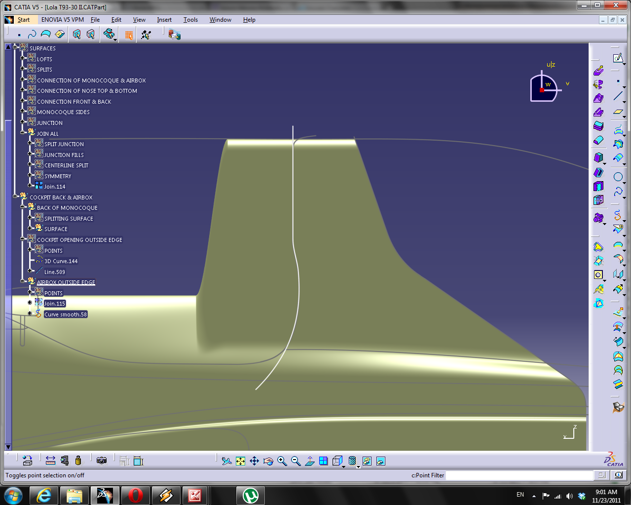
So split the monocoque with this shape. We'll want this shape to make a face as well, but not trimmed where everything is joined together

We're going to systematically chop this face up
Now for the airbox opening itself. I consider this, along with the nose, the sidepod openings and the engine cowling to be the defining shapes of a F1 car of this era. In other words, the dimensions of the cars are all roughly the same due to the rules, but these shapes are different on every car, so special attention should be paid to getting these right. It took me 7 tries to get this right, now I'll go into how to do it.
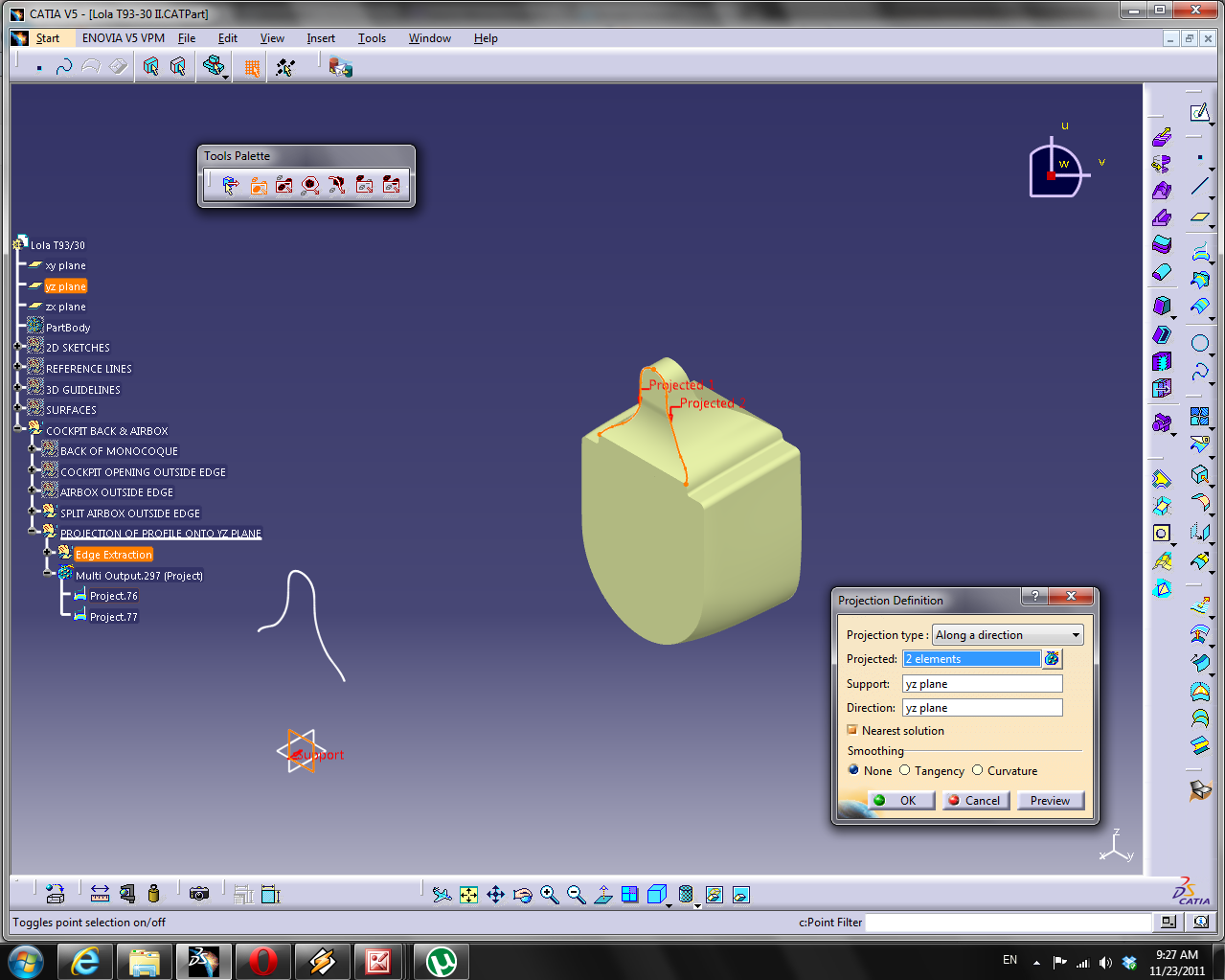
Extract some edges from the previous split and project them onto the yz plane
Join and smooth this

3d offset 23mm

Hide the original projection. Now I'm going to split this roughly where the lines are verticle.
By definition, this should be at this airbox guide

Draw a couple of lines and split it


Next up the profile of the bottom of the airbox opening.

I'm going to put some points on these lines, split the lines, and connect them with a 3d curve to create fillets

Join and smooth curve

We're going to have to repeat all these steps to do the back of the airbox opening (the side that faces the engine). I can't just sweep this surface, because the airbox opening has a different profile at the back.
Here is the back airbox opening with the front in the background

Project these profiles

It'll be useful to project the points used to create the fillets as well

Create some guidelines

Make a multi-sections surfaces with these profiles and guides. With closed profiles, I think it's good idea to set the extremum definition to the z component direction.

Hide the profiles and guides
Just a quick mock up to see what's done so far. That's it for me tonight

No comments:
Post a Comment